TaraNG : Resource Center
By: Trishna Mayal, August 8, 2019
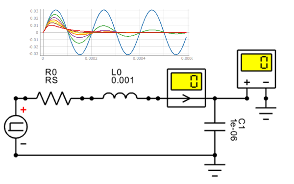
Series RLC Circuit
This is a basic design created within schematic mode of TaraNG. The schematic mode fascilitates drag and drop functionality to create circuits and block diagrams. In this example a series combination of resisitor, inductor and capacitor is designed to study the step response when to output is taken across capacitor. The tweek widget here is the one for value of resistor, which allows performance invistigation over variations in resisitor to examine the damping factor and thus circuit stability.
By: Swapnil Gaul, November 24, 2019
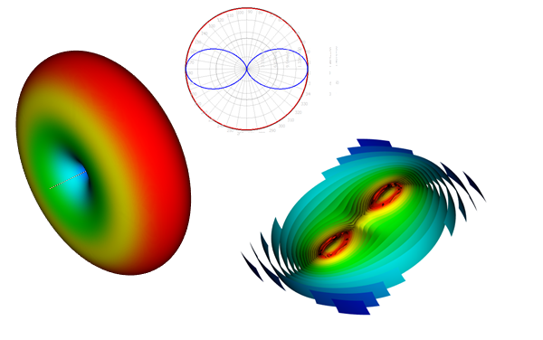
Half-wavelength Dipole Antenna
How to design a half wavelength dipole antenna operating at given frequency? Here’s a detail that lets you design this problem and run simulation to observe various 2D and 3D results. 2D Plots includes Port parameters, VSWR, Feed Power, Smith chart, Radiation pattern (polar plot) and 3D Plots includes Voltage/Current distribution, Radiation gain, Cut plane, Field contour, Flux lines. This exampple also demonstrates various export fascilities provided by TaraNG
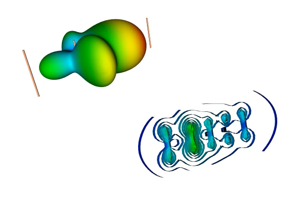
Yagi-Uda Antenna
How parasitic elements affects the antenna performance? How to achieve directivity and gain by properly choosing the number of parasitic elements and spacing between them? This example lets you design five element yagi-uda antenna to observe far field pattern and nearfield coplings say, current distribution and electric field countours. No surprise, this particular design of atenna radiated more towards the directors which are smaller elements in the design.
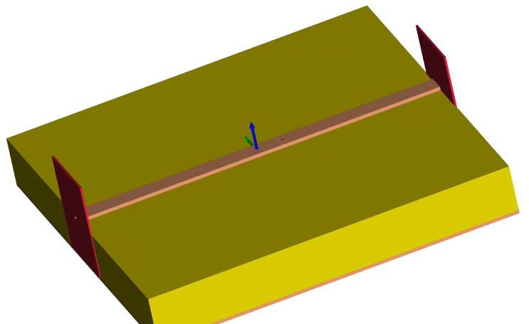
Microstrip Line
Microstrip line is the most popular types of planar transmission lines because of ease in fabrcation and integration with microwave componants. In this example a two port microstrip line is constructed to understand scattering characteristics by plotting S-parameters and smith chart. We can also observe changes in reflection coefficiennts by changing the dielectric constatnt of material embedded between the two conductors.
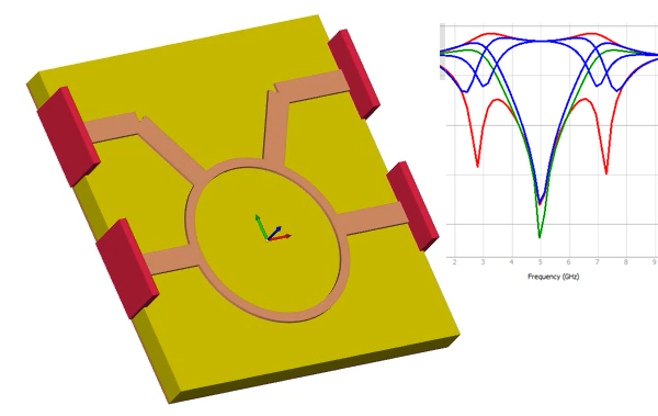
Rat-Race Coupler
How to design multi-port networks? Rat-Race is a four port device that has applications in mixers and phase shifters as well as phase splitter. After the simulation we will observethe S-parameter graphs to understand port coupling say, S11, S41, S31 and phase difference between port 2 and port 4, that is angle of S24. VSWR plot can also be observed.
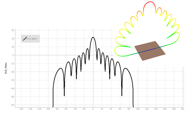
RCS of Rectangular Sheet
What will happen if electromagnetic awve hits on an objec? It will reflect back. RADAR is an application where we detect the objects by examining the reflected or scatterd waves. In this example a rectangular metallic sheet is considered as object under test. The EM wave is applied from different angles around the sheet and RADAR cross section area is calculated at respective angles. We can plot RCS in 2D plot as well as visualize it in 3D.
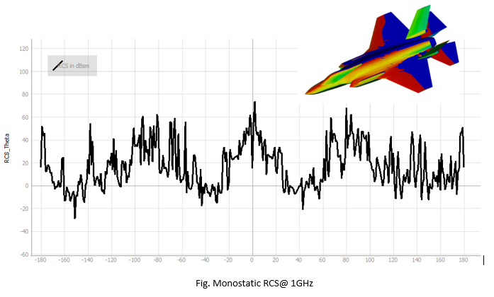
RCS of F-35 Aircraft
How solve large size problems? Yes, TaraNG is capable of solving large size problems when the wavelength of signal is very small compared to the dimension of design. This exmple demonstrates CAD import feature, we can directly import the compicated CAD files designed in third party softwares. Import the 'F-35 Aircraft' model (STL/OBJ file). Apply the electromagnetic proprties to the surfaces, like say, PEC, resistive sheet, composite layer so on. We can perfom both bistatic and monostatic RCS analysis at given frequency. Along with RCS the current distribution can also be vizualised in 3D after the simulation.
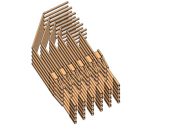
Interconnect Analysis
In high speed VLSI design the design of interconnect becomes major concern to IC designers. TaraNG is capable to accurately model the high freqiuency issues such as, skeen effect and proximity effect. This particular example demonstrates how to design a compex problem involving bundle of hundreds of rectangular bus bars called interconnects. The goal is to calculate parasitic coupling between the conducting bars and the resonant or eigen modes to understand the natural behaviour of the problem.
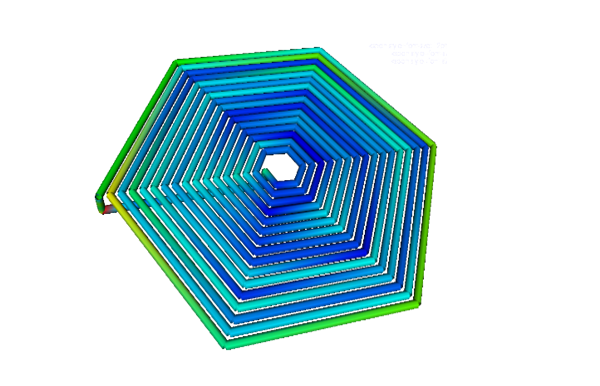
Spiral Inductor
Spiral Inductor is often used in radio frequency applications. Here the interest is to perform computation in near field also known as reactive field and to compute the parasitics. The parasitics will also include capacitance, at a certain frequency, the inductance and capacitance elements form a resonance. Surperisingly, after this frequency, the device functions as a capacitor not an inductor.
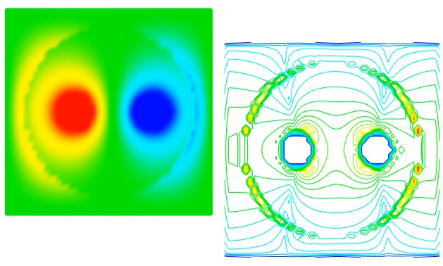
Electrostatic Simulation
In this example we will understand field distribution across cross section of problem by idealizing one dimension of 3D system. This problem is axis symmetric which consists of two parallel cables inclosed in a dielectric. One cable is applied positive voltage while the other applied the negative voltage. The electric field and field lines are plotted in 2D space. In this example we can also compute the capacitance between the cables.